What is Open Loop Control?
In open loop control the controller output is not a function of the process variable.In open loop control we are not concerned that a particular Set Point be maintained, the controller output is fixed at a value until it is changed by an operator. Many processes are stable in an open loop control mode and will maintain the process variable at a value in the absence of a disturbance.
Disturbances are uncontrolled changes in the process inputs or resources.
However, all processes experience disturbances and with open loop control this will always result in deviations in the process variable; and there are certain processes that are only stable at a given set of conditions and disturbances will cause these processes to become unstable. But for some processes open loop control is sufficient. Cooking on a stove top is an obvious example. The cooking element is fixed at high, medium or low without regard to the actual temperature of what we are cooking. In these processes, an example of open loop control would be the slide gate position on the discharge of a continuous mixer or ingredient bin.
Figure 1-1 depicts the now familiar heat exchanger. This is a stable process, and given no disturbances we would find that the process variable would stabilize at a value for a given valve position, say 110°F when the valve was 50% open. Furthermore, the temperature would remain at 110°F as long as there were no disturbances to the process.

Figure 1-1
However, if we had a fluctuation in steam supply pressure, or if the temperature of the water entering the heat exchanger were to change (this would be especially true for recirculation systems with a sudden change in demand) we would find that the process would move to a new point of stability with a new exit temperature.
What is Closed Loop Control?
In closed loop control the controller output is determined by difference between the process variable and the Set Point. Closed loop control is also called feedback or regulatory control.
The output of a closed loop controller is a function of the error.
Error is the deviation of the process variable from the Set Point and is defined as
E = SP - PV.
E = SP - PV.
A block diagram of a process under closed loop control is shown in figure 1-2

Figure 1-2
An important point of this illustration is that the process, from the controller’s perspective, is larger than just the transformation from cold to hot water within the heat exchanger. From the controllers perspective the process encompasses the RTD, the steam control valve and signal processing of the PV and CO values.
How the valve responds to the controller output and its corresponding effect on the manipulated variable (steam pressure) will determine the final effect on the process variable (temperature). The quality and responsiveness of the temperature measurement directly effects how the controller sees its effect on the process. Any filtering to diminish the effects of noise will paint a different picture of the process that the controller sees.
The dynamic behaviors of all of the elements in a control loop superimpose to form a single image of the process that is presented to the controller. To control the process requires some understanding of each of these elements.
Figure 1-3 depicts the heat exchanger under closed loop control.

Figure 1-3
What are the Modes of Closed Loop Control?
Closed loop control can be Manual, On-Off, PID, Advanced PID (ratio, cascade, feed-forward) or Model Based depending on the algorithm that determines the controller output based on the error.
Manual Control:
In manual control an operator directly manipulates the controller output to the final control element to maintain a Set Point.
In Figure 1-4 we have placed an operator at the steam valve of the heat exchanger. Their only duty is to look at the temperature of the water exiting the heat exchanger and adjust the steam valve accordingly; we have a manual control system.
While such a system would work, it is costly (we're employing someone to just turn a valve), the effectiveness depends on the experience of the operator, and as soon as the operator walks away we are in open loop.

Figure 1-4
On-Off Control: On-Off control provides a controller output of either on or off in response to error.
As an on-off controller only proves a controller output hat is either on or off, on-off control requires final control elements that have two command positions: on-off, open-closed.
In Figure 1-5 we have replaced the operator with a thermostat and installed an open-close actuator on the steam valve, we have implemented on-off control.

Figure 1-5
As the controller output can only be either on or off, the steam control valve will be either open or closed depending on the thermostat's control algorithm. For this example we know the thermostat's controller output must be on when the process variable is below the Set Point; and we know the thermostat's controller output must be off when the process variable is above the Set Point.
But what about when the process variable is equal to the Set Point? The controller output cannot be both on and off.
On-off controllers separate the point at which the controller changes its output by a value called the deadband (see Figure 1-6).

Figure 1-5
Upon changing the direction of the controller output, deadband is the value that must be traversed before the controller output will change its direction again.
On the heat exchanger, if the thermostat is configured with a 110°F Set Point and a 20°F deadband, the steam valve will open at 100°F and close at 120°F. If such a large fluctuation from the Set Point is acceptable, then the process is under control.
If this fluctuation is not acceptable we can decrease the deadband, but in doing so the steam valve
will cycle more rapidly, increasing the wear and tear on the valve, and we will never eliminate the error (remember, the thermostat cannot be both on and off at 110F).
PID Control: PID control provides a controller output that modulates from 0 to 100% in response to error.
As an on-off controller only proves a controller output that is either on or off, on-off control requires devices that have two command positions: on-off, open-closed.
As a PID controller provides a modulating controller output, PID control requires final control
elements that have can accept a range of command values, such as valve position or pump speed.
To modulate is to vary the amplitude of a signal or a position between two fixed points.
The advantage of PID control over on-off Control is the ability to operate the process with smaller error (no deadband) with less wear and tear on the final control elements.

Figure 1-6
Time Proportion Control:
Time proportion control is a variant of PID control that modulates the on-off time of a final control element that only has two command positions.
To achieve the effect of PID control the switching frequency of the device is modulated in response to error. This is achieved by introducing the concept of cycle time.
Cycle Time is the time base of the signal the final control element will receive from the controller. The PID controller determines the final signal to the controller by multiplying the cycle time by the output of the PID algorithm.
In Figure 1-7 we have a time proportion controller with a cycle time of 10 seconds. When the PID algorithm has an output of 100% the signal to the final control element will be on for 10 seconds and then repeat. If the PID algorithm computes a 70% output the signal to the final control element will be on for 7 seconds and off for 3 and then repeat.

Figure 1-7
While time proportion control can give you the benefits of PID control with less expensive final control elements it does so at the expense of wear and tear on those final control elements.Where used, output limiting should be configured on the controller to inhibit high frequency switching of the final control element at low controller outputs.
What are the Basic Elements of Process Control?
Controlling a process requires knowledge of four basic elements, the process itself, the sensor that measures the process value, the final control element that changes the manipulated variable, and the controller.
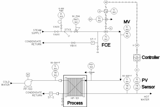
Figure 1-8
The Process:
We have learned that processes have a dynamic behavior that is determined by physical properties; as such they cannot be altered without making a physical change to the process.
Sensors:
Sensors measure the value of the process output that we wish to effect. This measurement is called the Process Variable or PV. Typical Process Variables that we measure are temperature, pressure, mass, flow and level. The Sensors we use to measure these values are RTDs, pressure gauges and transducers, load cells, flow meters and level probes.
Final Control Elements:
A Final Control Element is the physical device that receives commands from the controller to manipulate the resource. Typical Final Control Elements used in these processes are valves and pumps.
The Controller:
A Controller provides the signal to the final element. A controller can be a person, a switch, a single loop controller, or DCS / PLC system.
Detailed and good explanation on process control. Thanks for sharing this useful information.
ReplyDelete